Thursday, April 8, 2010

iar 560 assignment 6

Digital Manufacturing and Virtual Reality

 3D Printing:

 Advancements in computer-aided programs have made the design process much faster, and easier for the designer. 3D modeling can be done in the computer, saved as a PDF file, and sent to the machine of choice, a laser cutter, and cut for you in a minimal amount of time. Having a machine do all the cutting for you, leaves no room for human error, and allows the designer to put together multiple models in a short amount of time. This easy method of model building helps the designer to visually see and compare different models, in order to make a more informative, design decision.

 Rapid prototyping is the rapid creation of a part that may not have the accuracy or durability necessary in final applications. RP machines can create and object of virtually any geometric shape. Rapid prototyping machines use additive, layering technologies rather than subtractive processed that remove sections of material, such as milling (3D Printing 1). The main technologies for automated fabrication are stereolithography, stacking and laser cutting, robotically guided extrusion, laser sintering, and droplet deposition on powder. Stereolithography involves the use of lasers to solidify layers of clear or colored resin. The result is a solid, layered model made of epoxy. These models come out lightweight and translucent, and quite strong (3D Printing 2).

 There are some known problems with RP machines that create a barrier for artists and designers. The RP machines require 3D model information that includes surface thickness, which most commercial programs for Macs and PCs define only abstract surfaces, with no thickness information (3D Printing 3). On the positive side, automated fabricators can produce parts on demand, making environments such as space stations and lunar habitats easier to envision.

 When the Whole is Greater than the Sum of its Parts:

 Computer numerical control (CNC) milling machines have been around for decades, and have since been the go-to gadget for everyone, from product designers to architects who want their intricate designs fabricated fast (WWGSP 1). The use of computer-aided programs has made acoustical studies easier for the architect or designer. Using programs like Ecotect, a building design and environmental analysis tool by Autodesk, allows the designer to, “calibrate the different ceiling porosities and locate zones that needed adjusting to enhance acoustics. The quantitative data extracted from Ecotect informed a sophisticated parametric model. Those parameters were plugged into a series of scripts with Excel spreadsheets, and finally into a digital model and fabrication drawings” (WWGSP 2). Through Ecotect, the designers can study lighting levels of the ceiling treatment as well in order to get the desired lighting effect they were going for (WWGSP 3).

 Morphosis Prints Models

 “In many architecture firms, the introduction of computer-aided design has resulted in less reliance on hand-crafted scale models. However in some firms, CAD has enabled a happy marriage of new techniques with the old-fashioned craft (MPM 1). The 3D printer comes with its own software that sections the STL file horizontally into layers. “The 3D printer spreads one thin layer of powder over the print bed, then passes over the powder just as an inkjet printer head passes over paper. Where the digital model indicates a solid, the printer, using a modified inkjet printer cartridge, injects the binder cyanoacrylate.

After one pass, the print bed lowers by one thickness of powder, and the printer spreads another layer of powder and jets another pass of binder. The cycle continues until the top layer of the model has been printed. This process takes about five hours for a 6- by 6- by 6-inch (15- by 15- by 15-centimeter-) model. The actual time depends on the solid volume of the physical model. When the printing is completed, a 6-inch- (15-centimeter-) tall model is immersed 6 inches (15-centimeters) deep in powder. Raising the print bed, you remove the "part" and vacuum-clean out the excess powder, which can be sifted and reused” (MPM 2). One benefit of developing designs in CAD for in-house model fabrication has been that the Morphosis designers have necessarily improved the accuracy of their CAD modeling. And because they spend less time building physical models, they can spend more time on design thinking.

Sources:

1.      On 3D printing: Excerpt from "3D Input and Output" from The Computer in The Visual Arts by Anne Spalter, Addison Wesley Longman Inc. 1999, pp 317-321.

 2.      “When the Whole Is Greater Than the Sum of Its Parts” By Josephine Minutillo

http://continuingeducation.construction.com/article.php?L=5&C=588&P=1

 3.          “Morphosis Prints Models” by Martin Doscher

http://www.architectureweek.com/2004/0915/tools_2-1.html


Tuesday, April 6, 2010

Simulation: Building Chair

I had a lot of trouble with this assignment. I couldn't figure out how to push and pull each individual grid. This was a frustrating process to go through, but I think I almost have the form of the chair down. All I have left to do is figure out how to curve the form so that it looks realistic ergonomically. The legs should be easy enough when I learn how to create a curved silhouette. 

modeling:
Arne Jacobsen: Series 7 Chair

Process of Building Chair in Sketch up: 

snapshot 1
snapshot 2
snapshot 3
snapshot 4
snapshot 5
snapshot 6
snapshot 7
snapshot 8
snapshot 9
snapshot 10

Simulation: assignment 5

Simulation

Today, architects are increasingly relying on building simulation programs to aid in the design of a new structure. In terms of design and energy performance, the use of simulation programs, allows the designer to determine how natural phenomena such as, the wind, sun, and moon, affect the efficiency of the buildings structure. Simple studies such as, “the building orientation and shading studies were carried out by the architects using Ecotect, a software recently acquired by Autodesk. The three-dimensional architectural model was then transported into eQUEST, a sophisticated building-energy-use analysis tool initially developed as part of DOE-2, which allowed the engineers to optimize the mechanical and electrical systems, as well as the building envelope” (model behavior 1). The simulation program allows the designer to take a section of the exterior wall, in order to examine the façade orientation and overhang size to study heat gain. (Who would have thought this would ever be?). The architects who designed this building used a cone-shaped column, if you will, to provide structural support for the roof, as well as bring in daylight deep inside of the complex. These cones are also used to cool the interiors, by drawing warm air up and out of the building through their tips. The use of, “Computational fluid dynamics (CFD), which utilizes numerical methods to simulate the interaction of fluids and gases within complex systems, was employed extensively on this project to ensure that the flow of air through these cones produces the greatest cooling effect” (modern behavior 2).

Computer simulation programs are also being used to determine the amount of daylight that enters a space, and how it appears at different times of the day, or year. When designing an exhibition it’s important to keep in mind that, “a sense of subtle changes in outside conditions is desirable. But rapid swings in lighting levels are not” (sun shine 1). To determine the primary direction of illumination within the gallery space, an illumination vector analysis was conducted. As a result of the study, “designers refined the sunshade, adding a “kicker” at its bottom edge. This 3-foot-tall vertical element bounces light back to the south-facing wall, creating more uniform daylighting conditions” (sun shine 3). The art museum will consist of “a 30-foot-tall structure suspended from the roof trusses and floating about 10 feet from the gallery floor will surround the new skylight with frosted-glass fins (sun shine 3). This hanging element, together with fabric baffles enclosing the roof trusses and the large-works gallery floor, reflect, refract, and diffuse daylight passing through the new skylight and direct it to flanking side galleries. This strategy provides two levels of control. It prevents direct light from hitting artwork and controls diffuse and scattered light (sun shine 5).

Through computer simulation, critics were able to analyze Frank Lloyd Wright’s, Darwin D. Martin House based on direct observation and 2D architectural drawings. However, their conclusions lack insight made visible by 3D computer visualizations. These computer techniques reveal a unique relationship between the space of the Martin House and its fireplace. Only through computer analysis did it become clear that this relationship exists and what specific architectural conditions make it so. Within the computer environment, a model of the various volumes of the house was constructed in order to analyze the spatial conditions in Wright’s design. What was concluded is that, “the various volumes as defined by the structure interpenetrate. Because the areas of overlap can be perceived as belonging to multiple spatial orders, a complexity develops that enriches and activates the space of the house” (Comp. Visualization 1). Viewing the spatial model in elevation illustrates the vertical spaces where they exist between levels of the house. "Turning off" and removing from view any CAD layers that represent purely functional vertical volumes in this elevation—specifically the chimneys' ventilation spaces and all staircases—only one vertical spatial element remains that acts in unifying the levels of the house. This is the space encircled by the staircase of the main entry hall. The upward movement of the staircase surrounds and reinforces the verticality of this form, and where the stairway arrives at the second floor, an ornamental partition and landing trace the space. Vertical spatial volumes such as this one within Wright's residential work are rarely noted (Comp. Visualization 2). Conveying its critical findings through visualization, this study indicates just how the computer can provide a new way of "seeing" and evaluating architectural design. The ability of the computer to visualize an architectural concept such as space and its ability to selectively edit for content what we see provides us with a profound new manner in which to evaluate architecture. The computer is a valuable tool where its techniques can assist in creating a greater understanding of architecture and design (Comp. Visualization 2).

Sources:

Model Behavior: Anticipating Great Design

http://continuingeducation.construction.com/article.php?L=5&C=471

Let the (Indirect) Sun Shine In

http://continuingeducation.construction.com/article.php?L=5&C=406

Computer Visualization as a Tool for Critical Analysis by Mark Maddalina

http://www.architectureweek.com/2000/0705/tools_4-1.html  

Tuesday, February 23, 2010

Animation: assignment 4


In this animation I have made the door open as you walk into the space. I had trouble getting in to work with the interior space.

READINGS:

Summary:

 Animated graphics are used in virtually all time-based media work, from television, motion pictures, educational software, games, design, and art work. By using a sequence of slowly changing still images, the illusion of motion, or animation, is created. From the reading, I’ve found that the inbetween frames are critical in the animation process. Inbetweening is the frame, or image, that’s in between two frames. It helps create a cohesive animation, without showing the appearance of multiple frames. For example, if animating a ball in motion, as long as you have the three basic points to express that motion the start, end, and highest point, the computer program being used fills in the blanks automatically, creating a flawless animation (Animation&video pg6). To help with the spacing-out of the frames, there is a linear interpolation tool that allows you to calculate new positions at equal intervals along a straight line. Linear inbetweening uses the positions calculated with linear interpolation to position the object in the between frames (Animation&video pg6). As opposed to linear interpolation, which uses only straight lines, they’re us another tool, nonlinear interpolation that uses curves. This tool uses curves to define motion paths and other types of object transformations. By using this it greatly expands the usefulness and realism of automated inbetweening in the animation process (Animation&video pg10).

 Contextualize:

 After looking over the readings, I concluded that animated work implies motion, and motion implies space (Animation&video pg21). The relevancy of this software in the interior architecture program is crucial. Designing an interior space for a client is only half the battle. The way the design is presented and how well the designer conveys the space to the client is the other half of the battle. If the client is unable to understand the space from an interior perspective, they’re not going to stay interested very long. Without computer software programs, such as animation, rendering, and 3D modeling, expressing ones design is difficult. Without the realistic simulation of computer graphics and rendering programs, a designer would have a harder time selling their design work to a client or employer.

 Argument:

 Apart from the benefits of computer-aided software and design programs, there are some relevant issues related to this software. First off, computer rendering programs are very hard to grasp at first, and take a lot of practice to master. Seeing as the average designer most likely isn’t going to create amazing, photo-realistic renderings, the use of this software may not do their work any justice at all. If you aren’t extremely well with the design software, it can actually make your work appear worse than it actually is. However, it has kind of been accepted that computer renderings are considered better than hand-drawn. The use of these software programs has created inadequate thoughts related to hand-renderings. Hand-renderings are completely different than computer renderings and are great in their own respect. They can express more of the designer’s intentions for the space and what kind of feeling they are trying to portray. There are benefits to both types of rendering, and to create the most effective renderings, I believe computer renderings touched up by hand rendering gives the clean appearance of computer graphics, but a messy more realistically lived in space. Designers today are so reliant on 3D modeling and computer rendering programs that the practical hand-drawn approach has almost faded completely.


Tuesday, February 9, 2010

Research Project Investigation

ABSTRACT

 What I’m proposing to undertake for my research project is somewhat intertwined with my studio project for this semester. Currently, my studio is working on a residential project that incorporates retail as well. What we are trying to accomplish is an urban residence that will attract people of all ages, in hopes that the city will develop and flourish. For this classes project, I want to focus on perfecting the model of the exterior structure, using sketch up. I will then place the perfected model in its existing location in Albemarle, NC using a map from google maps that I will place in sketch up. After I have completed both of these tasks I will render the model in Podium. By doing all of these things, I will have advanced my skills in computer aided programs and my eligibility in the practice of interior architecture. All of the computer programs I have listed above are used in the interior architecture practice, and it would be beneficial for me to learn them at a higher degree.

 METHODOLOGY

 To accomplish this project, I will first use sketch up, which I am fairly well at, to create the model of the residence. I will then have to learn how to take a geographical map of the city of Albemarle and crop it to the scale I need, and figure out how to import that image into sketch up. Importing the image into the 3D scene in sketch up is going to take a lot of altering when it comes to scaling it to look realistic, as well as making the map match the scale of my sketch up model of the residence. I will have to play with the opacity, and transparency of the image to make it look like the model I’ve built belongs in the image of the city. I want it to look like its been there and that’s where it belongs. By incorporating daylight, the collaboration of the 2D image and the 3D model should come together to look like one. The shadows that are cast and the highlights in the environment will help blend the two together to look like one cohesive image. By using Podium to render the finalized image, the viewer should not be able to distinguish between the 2D graphic, and the 3D model.

 OUTCOME

 What I hope to accomplish from this research project, is more knowledge of computer aided software and rendering programs. I hope to accomplish a finished product that “wows” the client and gives them a holistic view of the architectural structure in the environment for which it was designed. By doing so, and doing it well, I hope to win over the client with the exceptional renderings that are comprised of, attention to detail done by transparency, and opacity to blend different mediums into one 3D image of the model and its surrounding environment.


Sunday, February 7, 2010

iar 560 assignment3

Computer graphics programs and advanced rendering programs are a key aspect of the interior architecture profession. Thanks to advanced research done by Donald P. Greenberg in the Program of Computer Graphics (PCG), many of the practical applications that are used by architects today, has been developed by Greenberg himself. His research led to the development of Lightscape, a rendering program capable of creating very realistic lighting effects by calculating the precise amount of light reflected from surfaces and materials within a scene: a very useful tool for designers and architects to use in the representation of their work.
Currently, research performed at PCG is focusing on three major areas. First, improving the user interfaces for architectural applications to make them more suitable for designers. Second, simulating the behavior of light in space and understanding the human visual perception system to refine the rendering algorithms. And third, developing methods for improving image capture and the quality of image-based rendering. For the architecture profession specifically, the PCG is concentrating on developing conceptual design tools, enabling architects to design in context, and enabling collaboration over the Internet. The development of the drawing-board sized device, which functions as both a sketchpad and display device, can be rotated and navigated in three dimensions and placed into an underlying 3D scene. This is a useful tool for designers of all types to help express design ideas to clients and help them visualize the interior space, as well as the environment in which it’s placed.
What I found interesting in the reading was the software’s unique ability to move smoothly between the realms of rough sketch, precision rendering, and real-time walkthroughs. The ability to sketch naturally and create accurate architectural drawings as well as 3D models connects the art of design directly with the science of architectural evaluation and development. Research has also allowed elaborate instrumentation to measure light within physical models as it reflects from surfaces and moves through various media such as air and glass. These measurements are then compared to the simulated light calculated by existing algorithms, which are then further refined according to the real world models. As a result, the software's ability to imitate visible reality increases in precision. This software will improve designer’s credibility when it comes to their work, and will help win over a job when there are multiple competitors.
Precision in light simulation, as in Lightscape, is important because it gives predictive credibility to the resulting renderings. For example, if an architect models an interior space that is supposed to be illuminated by a clerestory, a precise rendering will show whether the space does indeed receive enough light with that window configuration and orientation. If the space looks too dark, the architect using conventional renderers could simply modify the software settings to make the model look brighter. With a physically precise simulation, the architect must adjust the window size, shape, or the position of the glazing or the color or reflectivity of the interior surfaces to improve the quality of light in the space. In other words, the problem won't be solved until the architectural elements are correctly designed. This helps interior designers and architects to see things they may have not had the chance to see before. They can now fix problems when alarmed by the computer, instead of noticing it too far into the design process. This software will help tremendously with time constraints and also help the designer work faster.
A third area of research is in "image-based" techniques. These techniques are already familiar through currently available technologies. For example, a digital photograph of an object or material can be "texture-mapped" onto the surface of a geometric model, giving the rendering the appearance of realism without requiring much geometric complexity. Another common application is in the animation technology pioneered by Apple Computer with the QuickTime VR format. Using QuickTime VR, several still photos taken at regular intervals for 360-degrees around a stationary viewpoint can be stitched together to create a panorama. Viewers can "look" around a 360-degree space by moving the mouse. The application is becoming popular for displaying architectural spaces on the Web.
The advancements in computer software have made modeling and rendering of architectural environments more realistic and believable for the client. Having the ability to apply lighting effects that are accurate appeals to the client more, as well as helps give them a better idea of the space to be. Now being able to view the whole space in its entirety with the look around of 360 degrees helps the client feel as if they are walking through the space. Giving them the feeling of the space with these 3D renderings is a positive step toward the future.

Sources:
"Rendering 3D worlds - 3D Geometric Graphics II" by Anne Spalter, Addison Wesley Longman Inc. 1999, pp 257-293.

"Once and Future Graphics Pioneer", B.J. Novitski
http://www.architectureweek.com/2000/0913/tools_1-1.html

"Once and Future Graphics Pioneer Part II", B.J. Novitski
http://www.architectureweek.com/2000/0920/tools_1-1.html

Wednesday, February 3, 2010

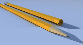
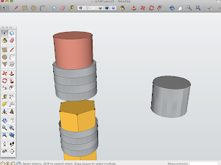
Object to model: Pencil


iar 560 assignment2

After reading both articles, I have a new understanding for 3D modeling and everything that it consists of. After research I’ve come to find that there is so much more complexity to modeling than I knew about, yet more opportunity at the same time with all the different modeling programs and what they have to offer.
The purpose of 3D models is to use 3D geometry to define 2D and 3D shapes. These descriptions are then rasterized to create images for raster-based screens and printers. This is a very useful method for designers, architects, and mechanical engineers, especially when it comes to modeling their work to the best of its ability. However, there are challenges with 3D modeling programs and their unrealistic representations of day lighting and its effects on object surfaces.
Designers and model-makers have an important decision to make when deciding which features of the real object or other entity to incorporate in a 3D model. A good model captures information and relationships vital for a specific purpose, whether that purpose is functional or aesthetic (Building 3D Worlds pg.2). Today, scientific visualization allows visualizing a model in a 3D environment possible. Data from this model reveals information that would be nearly impossible to gather from looking at towering piles of numerical printouts (Building 3D Worlds pg3). There is also behavioral modeling, which gives the designer the ability to view an objects behavior in an environment, such as a stone falling to the ground if dropped, moving in an arc through the air when thrown, or colliding with other objects (Building 3D Worlds pg3). Artists and scientists still ponder the question of, when is a model good enough? A model should show 3D spatial information such as depth, but behavioral modeling and the modeling of other aspects of 3D reality, such as sound physical feedback, also can be important.
Visualization is the modeling of objects interiors. Objects interiors can be very useful for engineers and designers who want to understand the effects of stress or temperature on their materials. Advancements in computer-aided design have made 3D modeling possible for designers with voxel-based modeling. However, in order for voxel-based modeling to happen personal computers will need more memory, they will need faster algorithms for drawing voxel-based models on the screen, and better input and output devices are required (Building 3D Worlds pg5).
There are several important terms in the 3D modeling world that are important to know as designers, Boolean operation, primitives and sweeps. Boolean operations is adding and subtracting of shapes that can be performed with solid objects (Building 3D Worlds pg8). Primitives are 3D shapes that are not composed of any subsidiary 3D forms (and thus are usually quite simple). Primitives are pre-made and are defined in concise ways that take up less storage space. Programs use certain primitive shapes as useful starting points for creating components of more complex objects. Sweeps are Basic 3D forms, which can be created by drawing a 2D geometric shape, referred to as a profile, and then sweeping it through space to describe a 3D form (Building 3D Worlds pg7). All 3D programs understand polygons, and most 3D file-exchange formats are based on polygonal descriptions. For cube like forms with flat surfaces, a polygonal representation describes the desired shapes quite accurately. For curved forms, however, such spheres and cylinders, a polygonal representation can only approximate the desired surface. You can render polygonal models of curved objects to look smooth, but to model a curved surface more accurately you need real curved shapes, not linear approximations (Building 3D Worlds pg9).
To help make 3D modeling of real world objects easier, especially those in nature, which don’t look like a collection of geometric primitives or sweeps, digital clay and 3D sculpting have evolved. An approach to modifying simple objects called digital clay, or 3D sculpting (not related to volumetric sculpting), lets you click and drag on polygon vertices. By pushing and pulling on the vertices and connecting lines of objects polygonal mesh, you can warp a polyhedral object into various bent, twisted, and distorted new shapes (Building 3D Worlds pg10). Another useful tool for designers was the invention of Fractals. Many natural forms could not be described geometrically until the invention of fractals. Fractal objects mimic natural structures in a nonspecific way. Developed fractals as a geometric way to express seemingly irregular “non-geometric-looking” forms such as trees, coastlines, and clouds by noticing that they exhibited, at many levels of detail, patterns of self-similarity- the structure of a small section resembles the structure of the whole object (Building 3D Worlds pg16).
Particle systems is also a useful tool for designers, when it comes to modeling, for example, smoke, fire, air, bubbles, and the like which are not really single, distinct objects like a chair or a tree or self-similar structures like a plant, but can be thought of as dispersed particulate matter (Building 3D Worlds pg17). Such phenomena can be successfully represented with particle systems, or algorithmically controlled masses of individual shapes that are automatically created with hierarchies that can control movement of the entire system. (Building 3D Worlds pg18-19) Partical systems can be used to create natural forms such as plants and trees by defining the particles to look like branches, petals, or even parts of blades of grass.
Considering geometric modeling, a good data structure is one that is well formed, while balancing the attributes of generality, efficiency, and completeness in a manner that matches the needs of the application for which it is used. There are three general categories of geometric modeling, wire frames, surface models, and solid models. Wire frame models represent only the edges of shapes, leaving to the viewer the task of inferring the volume and other properties of the shape and form theses outlines. Surface models represent the vertices, edges, and faces of an object, but the structure they impose on these components is rather limited. They are relationships between the faces themselves; essentially collections of unrelated polygons (geometric modelingpg2). This approach supports hidden-line removal, the process where only those parts of the shape that are visible from a given point or view are displayed on the screen. Makes it possible to see the relationship between them. Lastly, solid models are the most complete, well formed, and general of all methods used to represent shapes. Its efficiency depends on the particular approach used to implement the model. Its surface, volume, and geometric properties can be calculated (geometric modelingpg3).
The use of these 3D modeling programs has evolved into something that designers and architects use daily to represent and communicate their work to their peers and the public. Without these programs, the modeling of complex structures would take far longer, and it would be much harder to visualize and express to other people. However, the difficulty of learning these programs is a downfall. Without the resources to be taught how to use these programs, trying to figure them out by yourself is nearly impossible. When you do know how to navigate these complex, 3D modeling programs you can get some extraordinary results and are very realistic.

Sources:
"Building 3D Worlds – 3D Geometric Graphics I" from The Computer in The
Visual Arts by Anne Spalter, Addison Wesley Longman Inc. 1999
On Geometric Modeling: Excerpt from “Modeling”. Architecture’s New Media by Yehuda Kalay, The MIT Press, 2004

Thursday, January 28, 2010

iar 560 assignment1


Based on the two readings, “Computing in Architectural Design,” and “The Pioneers of Digital Art,” it is obvious that design has evolved tremendously through out the century. In the first article, “Computing,” Leonardo Davinci thought about design and ergonomics as early as 1490, with the drawing of his Vitruvian Man. By looking at the scale of the human body and how it reacts to architecture ergonomically was a huge step forward in art and design.
One of the first men to approach computer-aided design and one of the founding fathers of digital media, was Ivan Sutherland in the 1960’s with his creation of the sketchpad. This program was a man-machine graphical communication system. This program was a way to integrate the evolving design and analysis programs. By using a light pen to sketch a design idea, the program would refine the sketch into a perfect drawing by straightening the lines and squares in the drawing using a built-in assumption about the shape the user intended to draw. This is a very relevant program for any design profession, which would be very helpful for those who may not draw well enough by hand to get their design across, well enough to be believable by peers.
In the mid-1960s, artists and engineers united to make an exhibition about art mediums and technology, and the computer demonstrates this radical extension. Technology and art have almost collided today to become an interface to display work, express ideas, and share design to the world. This step was huge for the design world and its future. However, the problem in the 1960s and 70s, was gaining access to the giant computer systems, which remained in only three main locations; military, industry, and research universities. So it was hard for the average designer to use these advancements; advancements that design students today can take full advantage of.
In the 1970s, computer-animation was beginning to interest designers. Advanced research and experimentation done by Charles Csuri, allowed him to pull up hand-drawn images from the computers memory and animate them on the screen with a light pen. This idea of repeated objects to form an action is similar to that of a flipbook or similar to today’s movies, commercials, virtual tours and so on. The advancements have made expressing design to the world a lot easier. Also in the 70s, the Aalto was invented, which is a notebook-sized computer. Before the Aalto, computers were machines housed in a central facility, as talked about above. So in essence, the Aalto was the first personal computer, however it was never successfully marketed.
In the 70s, computers began to appear in architectural practices used for computer-aided design. CAD took two different approaches or routes with its program. The first was geometric modeling, which was geared toward supporting the needs of the construction industry, a very useful tool in seeing and representing a designers work. Secondly, the program was used for complex curves, complex geometrics, building description, and space planning. Computer-aided design was becoming a prominent aspect of the design world. Architects during this time were fascinated by the ability of these computing machines, which were now capable of drafting, a skill that took many hours of concentration and tedious drawing by hand. Now drafting is just a click of a mouse away and can be completed in a timely fashion with less room for human error. Drafting was a key aspect of the new computer graphics program, but the ability to conceive and communicate ideas to other designers and clients had just gotten much easier.
Auto Desk, known as drafting and modeling systems has evolved over the past few generations. The first generation CAD software dealt simply with polygons, solids, NURBS, and blobs. The second-generation version of auto desk, the commonly used version, focused on building specific software objects as doors, windows, columns, and stairs. Today a 3rd version of Auto Desk is under development, which focuses on simulating dynamic behavior of buildings, the movement of people, and the natural environment; leading towards virtual environments, a challenge for the professions of architecture, town planning, and interior design of the future.
Finally, in the mid 1980s the personal computer was actually put on the market. The arrival of the Apple and Macintosh was a huge step in computer graphic-based machines. The Mac allowed flexibility for varying fonts, styles, and sizes, which played a crucial role in the new era of layout and design. Well into the 1990s, Macs were dominating the world of graphic design, multimedia and education. However, the problem with the original Mac is it was only available in a black and white display. Three years later, the Mac two hit the market, which had the advantage of color graphics and digital imaging. This was an important step for the world of design and graphics and how to best display the work of the designer.
Entering the 1990s, a whole new revolution of digital modeling and animation was introduced. Video games had hit the market, with the first arcade game, “Pong.” This led to the experimentation of web-specific art and virtual realities. As of today, the world of design lies in the hands of computer graphics and design programs. Computers and virtual environments is the next step toward the future of design and inhabitable physical environments. Computer programs are in the process of being able to control temperature, humidity, and lighting security systems all at the touch of a key or mouse. Virtual environments are the new, living “space.”